Colecovision Custom Controller
The controller interface board is the electronic circuit board inside the colecovision controller where all the buttons / joystick and the cable all connect to inside the control pad.
![]() Note: You do not have to create an interface board from scratch. If you have an old controller that you no longer need / want, you can open it up and use the circuit board within instead. However please note that if you want to use any of the numbers on the number pad you will have to use the entire number pad itself and incorporate it into your design or work out a way of tapping into the interface board for each number that you would like to include.
Note: You do not have to create an interface board from scratch. If you have an old controller that you no longer need / want, you can open it up and use the circuit board within instead. However please note that if you want to use any of the numbers on the number pad you will have to use the entire number pad itself and incorporate it into your design or work out a way of tapping into the interface board for each number that you would like to include.
At this point you have 2 options. You can assemble the controller board from scratch yourself, or you can sacrifice an old controller, and you use the controller board inside for your project (easier option).
Jump to:
Option 1: Make your own interface board from scratch
Option 2: Original Colecovision Controller Hack
Option 1: Making Your Own Interface Board
Unfortunately we must start with one of the trickier parts first, as the other components hook up to the interface board, it makes logical sense to begin with the interface board itself. The board is relatively simple to work out. If you have a basic understanding of electronics, you shouldn't have too much trouble assembling it.
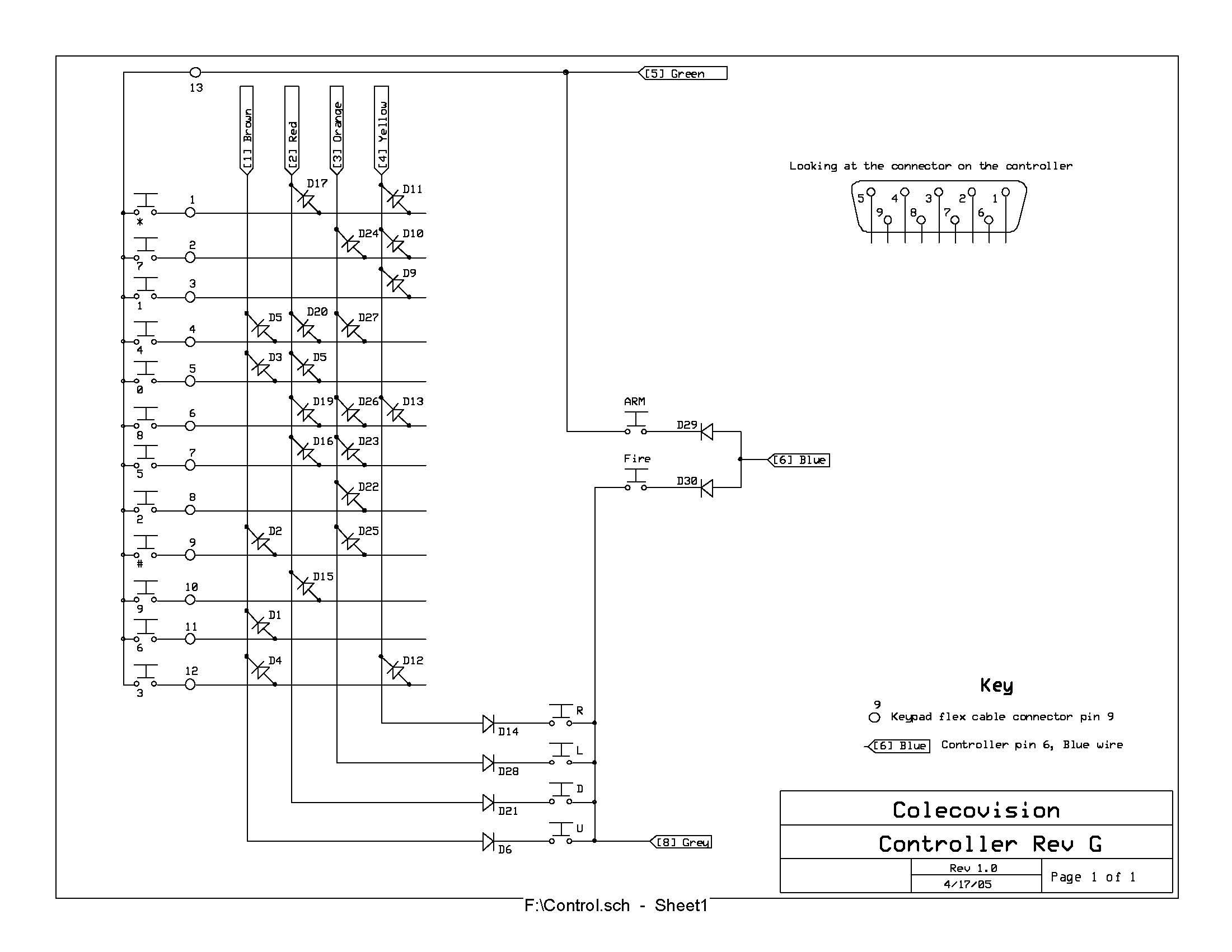
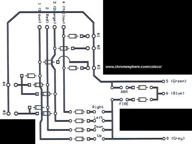
The cable that connects the controller to the colecovision console has 9 individual wires inside of it, 7 of which are used. This is called a DB9 Cable or "D-Sub 9 " cable. Each one of these wires is a different color. You must hook each color up to the respective color on the interface board as shown in this schematic:
![]() Download Colecovision Controller Schematic: JPG or PDF
Download Colecovision Controller Schematic: JPG or PDF
I would strongly suggest printing this schematic as you will be referring to it constantly.
Diodes
The only electronic component used in this board is a component known as a "diode". A diode is an electronic device that allows flow of current in only one direction. Like a one-way street, current will only flow in the direction that the diode will pass. This picture shows how a diode looks both on a circuit schematic and as a physical object:
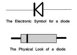
If you have already viewed the schematic (download above) you would have seen the diode symbols used in the circuit. The band on the physical diode is postioned on the cathode end. It is important when you make your PCB to solder these diodes the right way around.
There are a variety of different diodes available for different applications. Some are used in high-voltage circuits however the ones that we need are known as "signal diodes". These are designed to pass a low level of current or 'signal'. They are very inexpensive and are used in fast switching applications (like bashing an attack button for instance).
Project PCB
You will need a Printed Circuit Board (PCB) to solder your diodes and cabling onto. If you are making only one board i would recommend using a project PCB for your controller interface board. You can buy project PCB's in varying sizes from your local electronics shop which come with a multitude of tracks and holes for you to work with which means that you dont need any circuit board etching tools, artwork, or an exposure bed!
![]() Because this controller circuit isn't very big, you should only need a small to medium sized project PCB, if you plan your circuit with a degree of conservation.
Because this controller circuit isn't very big, you should only need a small to medium sized project PCB, if you plan your circuit with a degree of conservation.
Examining the Schematic
You will need to follow the tracks in the schematic and plan out and solder your diodes and cabling in the same way as whats illustrated in the circuit schematic.
The interface board schematic includes the number pad portion of the controller (left-hand side of the circuit). If you do not wish to have any of the number pad buttons on your controller you can disregard this entire matrix section of the schematic. This is a good option if you are not confident with electronics. The directional buttons of the circuit will need to connect to the other end of the track that goes through the numberpad matrix, ie: Right - yellow, Left - Orange, Red - Down, Brown - Up. You can see these 4 wires at the top of the numberpad matrix. Although these tracks go through the number matrix in a criss-cross fashion, they are only connected by the diodes.
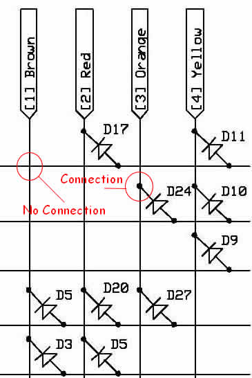
The numberpad matrix is only connected by each diode
Click to Enlarge
Also please be aware that if you decide to include any of the numbers of the number pad, make certain to use the numbers underneath the button symbols in the schematic, which are not in sequence, NOT the track numbers which ARE in sequence. This is shown in this edited extract of the schematic (the blue box has the correct numbers and the red box has the incorrect numbers / track numbers):
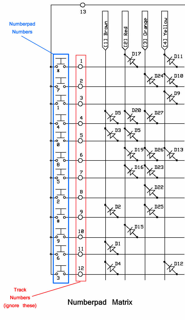
Correct and Incorrect numbers of the number pad
Click to Enlarge
The Numberpad - How it works
As previously mentioned, in the numberpad portion of the circuit (pictured above) where the tracks are criss-crossing, these tracks are not connected. The only connection that is made is from the diodes for each number.
The colecovision interprets a number by receiving different combinations of signals on the 4 coloured wires: Brown, Red, Orange and Yellow. So for instance, if the colecovision receives a signal on the brown and red wires of the db9 cable but nothing on the orange and yellow lines, it would translate this as the number Zero on the number pad. The cable providing the signal is the green cable which is pin five on the connector.
Planning the Interface Board Circuit
If you plan the circuit carefully, following the tracks around the schematic and planning these on your project PCB, you should be able to create a working circuit without much trouble. Just remember to plan it out on paper before you start soldering and test the parts that your not sure about first.
If you arent very good with electronics, you could make a PCB without any of the numbers from the number pad included. This will make the circuit much more straightforward or try the controller hack method instead which is even easier (see below).
Track Artwork for Etching
A friend of mine has provided a track layout for those looking to etch their own PCB's. The track layout includes the 2 fire buttons, the directional joystick and the numbers 1 to 5 of the number pad. Thanks Fred! I'm sure this will help alot of people out there with their projects!
![]() Download Track Layout Artwork: JPG file or PDF file
Download Track Layout Artwork: JPG file or PDF file
Option 2: Hacking an old controller
Disclaimer: Follow these instructions at your own risk. Responsibility for damage or loss of equipment due to modification is not held by this site.
If your not completely confident making an controller interface board from scratch you can remove one from an existing controller and use it instead. Wiring the 2 buttons and a joystick from this board is pretty simple. If you want to use the numberpad from your donor controller, you will have to leave it attached to the controller board itself, and incorporate this into your design.
The interface board in these pictures is from a previous controller hack that i had undertaken, before i decided to make an interface board from scratch.
Wiring the Buttons to the hacked controller board
The fire one and fire two buttons are simple to wire into your circuit. As the old colecovision buttons were essentially just switches, all you need to do is connect one pair of wires to each of the buttons that you are using. These are not polarised. You will need to de-solder the original buttons in order to solder in new wires with which to connect your buttons to. The mounting holes you need to connect your wires for the 2 main fire buttons are shown here:
Wiring the 2 fire buttons on the hacked controller board Top and Bottom View
Click to enlarge
![]() Note: The solder points for the 2 fire buttons are located very close. Make sure not to connect these 2 points together, otherwise your switch will not work.
Note: The solder points for the 2 fire buttons are located very close. Make sure not to connect these 2 points together, otherwise your switch will not work.
Wiring in an arcade joystick
I talk more about arcade joysticks and how they work in the Arcade Parts Page of this website, but for this section i will be explaining how to wire them up to a hacked controller.
As this controller board is a little different to the assembly method controller board, we have to wire it up a little differently. We will be using a wiring technique common in the arcade industry called "daisy-chaining". Basically what this means is that all the 4 "COM" terminals on the microswitches are connected in a daisy-chain fashion. (See the Arcade Parts Page for more information about microswitches). This edited picture shows a joystick, with only the grounded daisy chain cable connected:
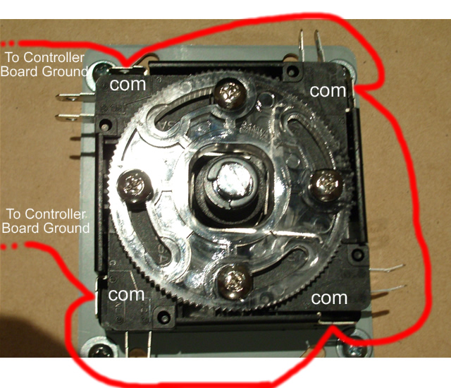
Arcade Joystick Ground Daisy Chaining
Click to Enlarge
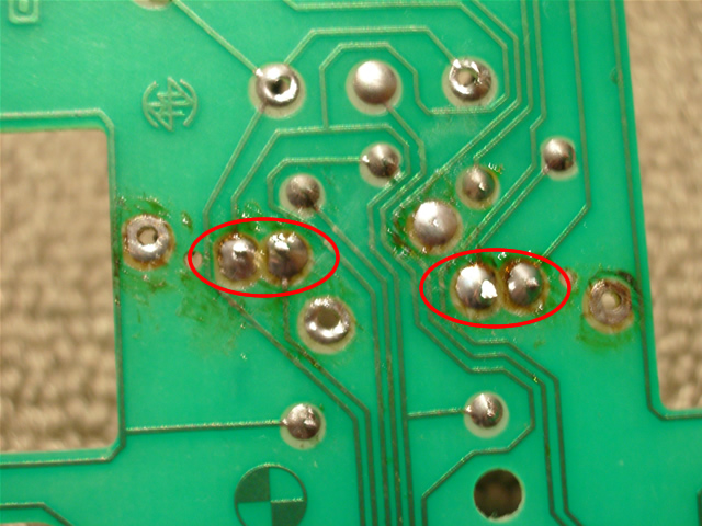
The 2 ends of the daisy chain connect up to any 2 points on the controller boards ground track. You could think of a ground as a water mains under your house, where all the water goes after it has been used. The ground track can be seen in this photo. The arrows point to the track and the circles highlight the ground tracks solder points:
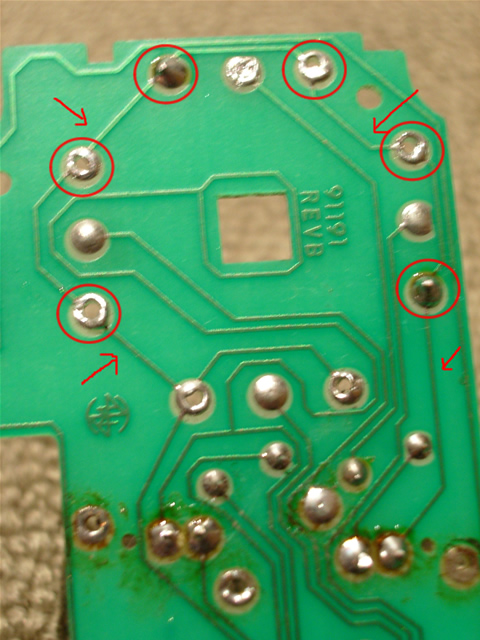
Joystick Ground Track
Click to Enlarge
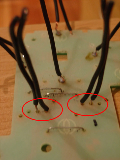
After you have wired up the ground track to your joystick, its just a matter of working out which of the 4 directional points go to which of the microswitches on your joystick. The colecovisions controller board is easy to work out; up is at the top, left is to the left etc but arcade joysticks aren't layed out quite so easily. You will have to experiement with the joystick. Hook up the 4 wires to the joystick. Test it and record your results. Switch off the console, rearrange your wiring, etc, until you have wired it up in the correct combination. This photo shows the four directional buttons solder points:
![]() Left and right are on their opposite sides because we are looking at the bottom of the controller board ie it is flipped over.
Left and right are on their opposite sides because we are looking at the bottom of the controller board ie it is flipped over.
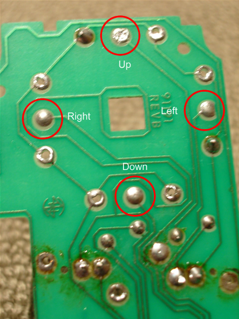
The Four Directional Solder Points Labelled
Click to Enlarge
So the total number of wires for the joystick section of the hack is 6, 2 ground (daisy chained around the 4 COM terminals of your joystick) and 4 for the directions, up, down, left, and right.
If you decide you would like to incorporate the numberpad into your design you will need to use your original numberpad or wire into your hacked controller directly. I have found this flash picture of a controller, which is interactive and shows you what tracks you are using when you press different buttons etc.
![]() If you dont incorporate the numberpad you can still start the game using the numberpad on an original controller plugged into controller port two on the console.
If you dont incorporate the numberpad you can still start the game using the numberpad on an original controller plugged into controller port two on the console.
Congratulations! If you have made it this far, then you should have a working controller board hooked up to arcade parts.